Selection guide
Wire Harness Manufacturing: From Drawing to Final Test
Plan wire harness production from the drawing: cutting, stripping, seals, crimping, housing insertion, taping and final electrical checks.
Read engineering guide →Wire harness testing machines answering four questions: did the crimp hold (pull testers from a 500 N dial gauge to a 10,000 N automatic frame), is the crimp metallurgically sound (cross-section analyzers at 30–312X on 0.01–150 mm² wire), does the harness conduct and insulate (128-point continuity testers, DC 200–700 V insulation, power-plug hi-pot testers), and is every wire in the right cavity (vision inspection in under 0.25 s). Send your terminated samples and we run the tests on video before you order.
Terminal pull-force testing measures mechanical retention; crimp cross-section analysis examines the joint geometry. For the assembled circuit, compare continuity and insulation testing. These methods answer different questions and should be matched to your acceptance specification. Use our wire harness test equipment selection guide to define the test, fixtures and sample plan.
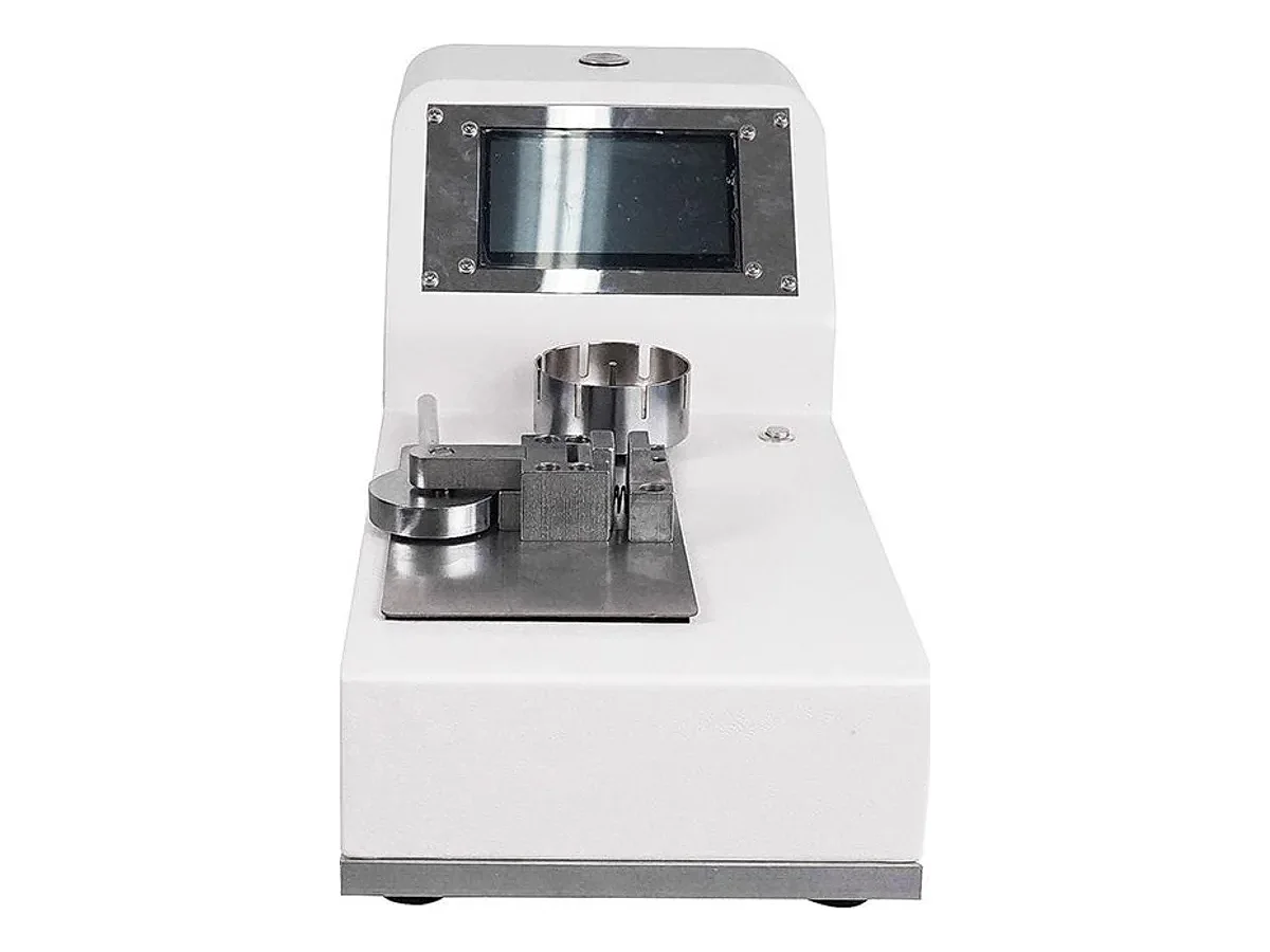
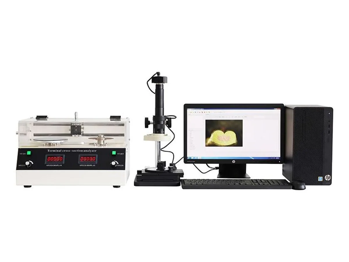
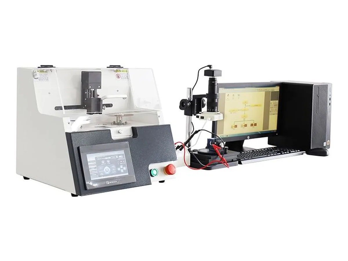
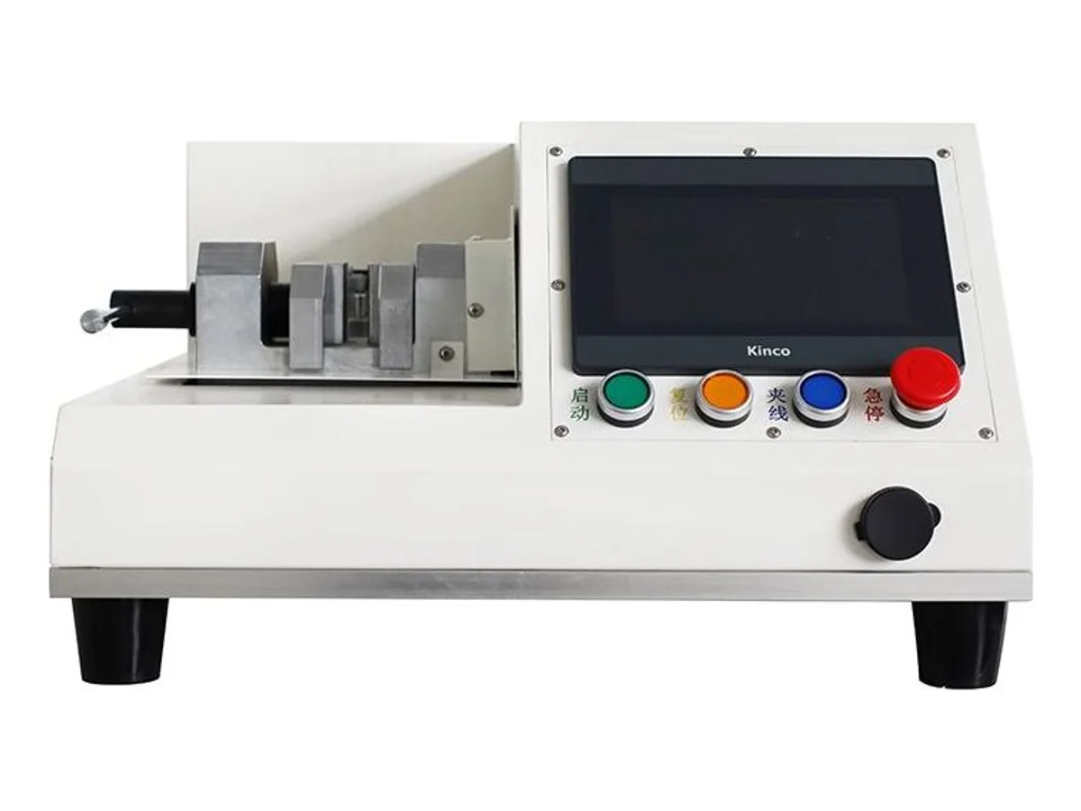
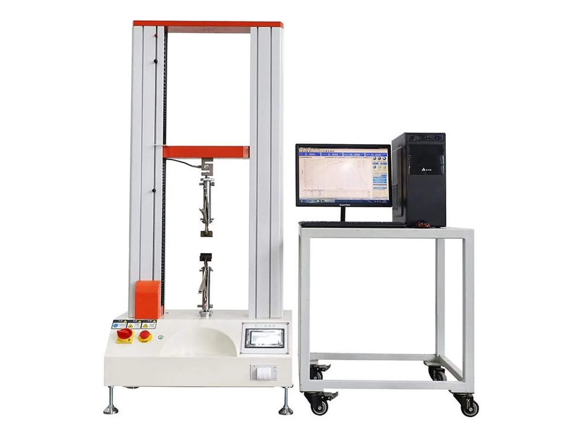
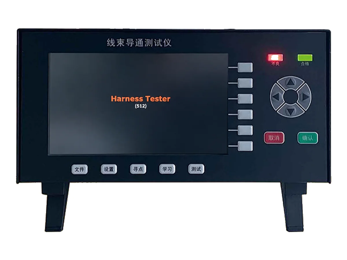
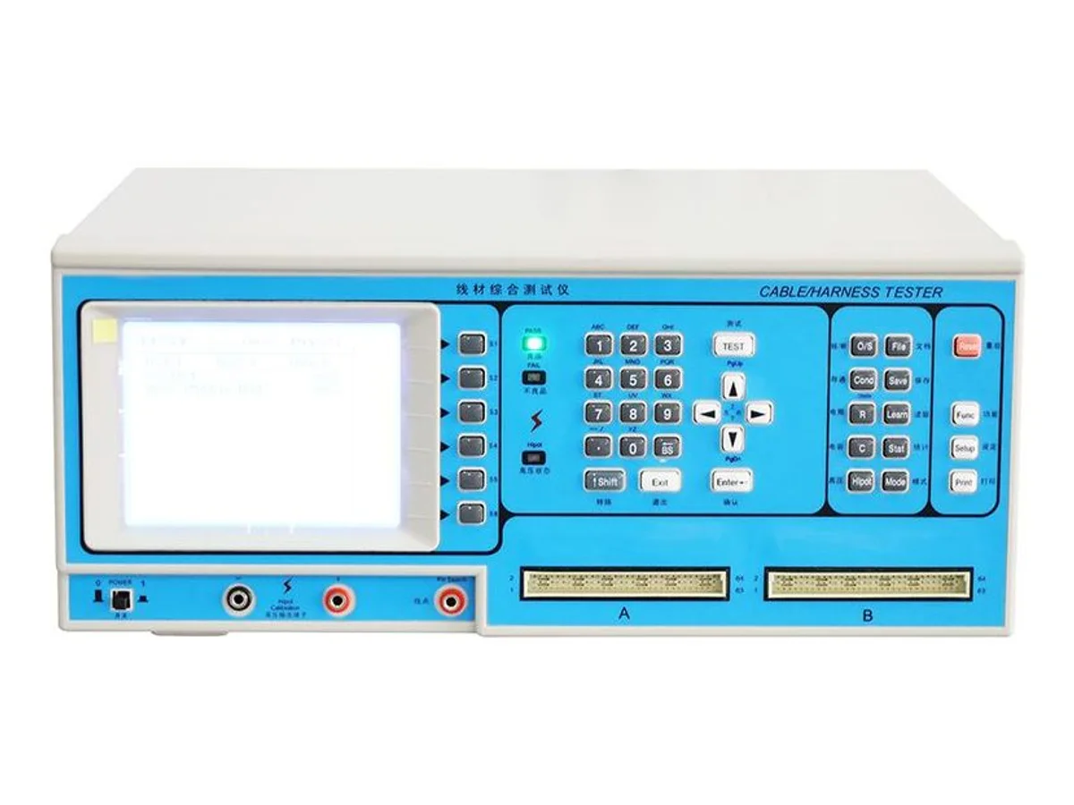
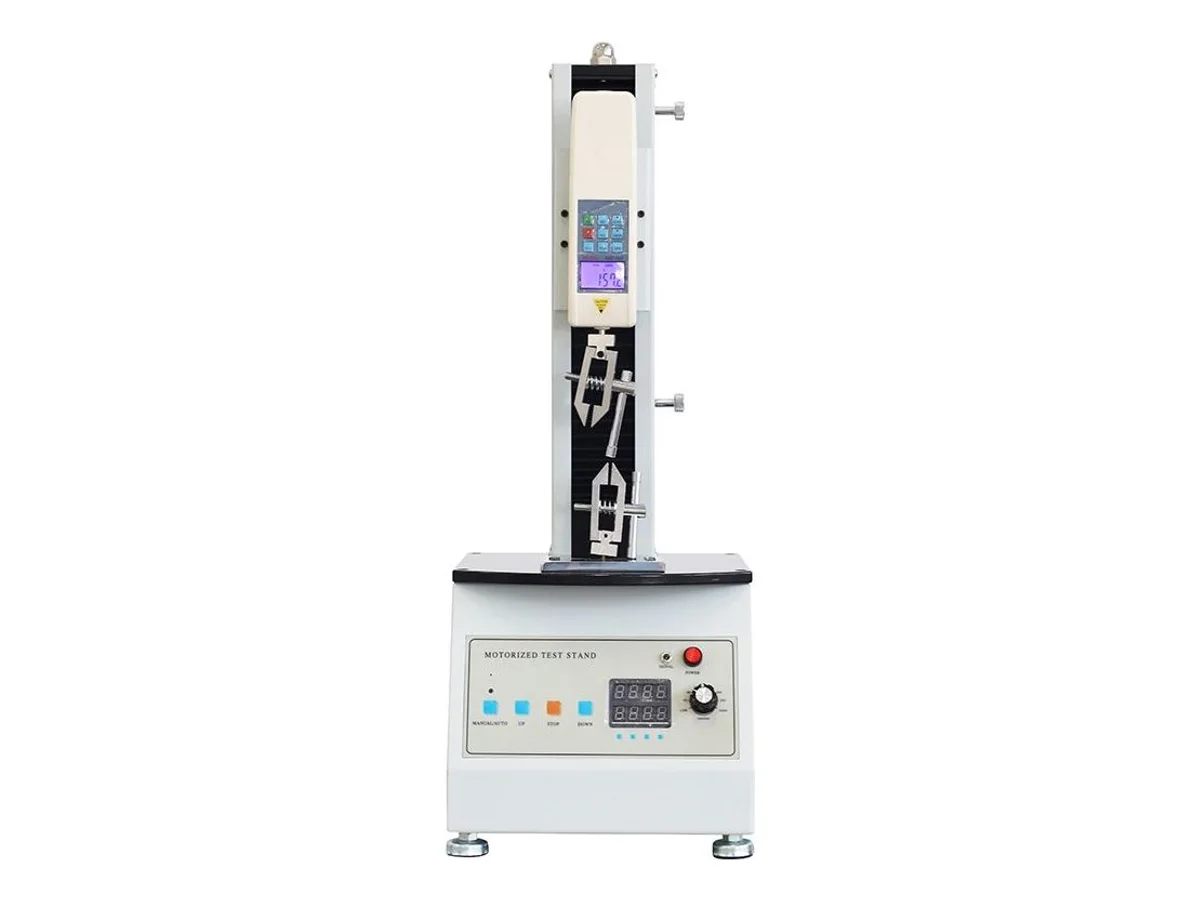
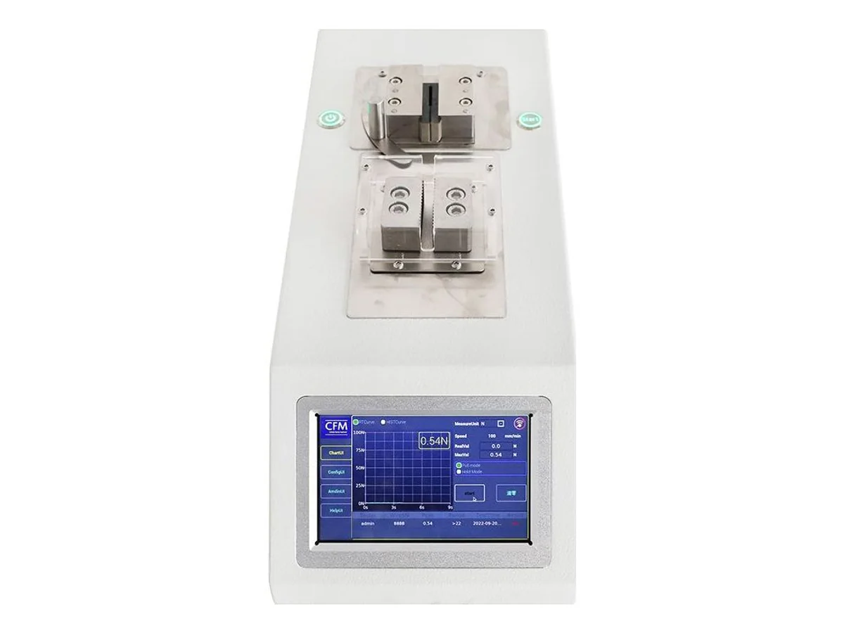
Did the crimp hold? Pull testers measure terminal pull-off force: the WM-817 is a 500 N dial-gauge unit for spot checks, the WM-820 automates the same class with a touchscreen, ±0.04 N accuracy and UL test values, and the WM-811 clamps automatically and pulls to 10,000 N for heavy lugs. Is the crimp metallurgically right? Cross-section analyzers cut, grind, etch and measure the joint at 30–312X: the WM-813 covers 0.01–30 mm² (optional 150 mm²), the WM-818 integrates cutting and grinding in one benchtop unit up to 120 mm². Does it conduct and insulate? The WM-814 tests 128 points for conduction (0.1–50 Ω), insulation (1 MΩ–1 GΩ) and components under DC 200–700 V; the WM-823 tests finished power cords for polarity, insulation and hi-pot on two heads. Is every wire where it belongs? Vision systems verify color and sequence without touching the part: the WM-815 in under 0.2 s, the WM-816 for two-row connectors in 0.25 s.
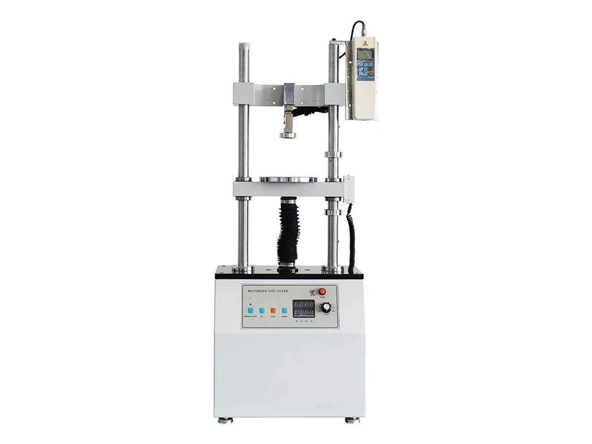
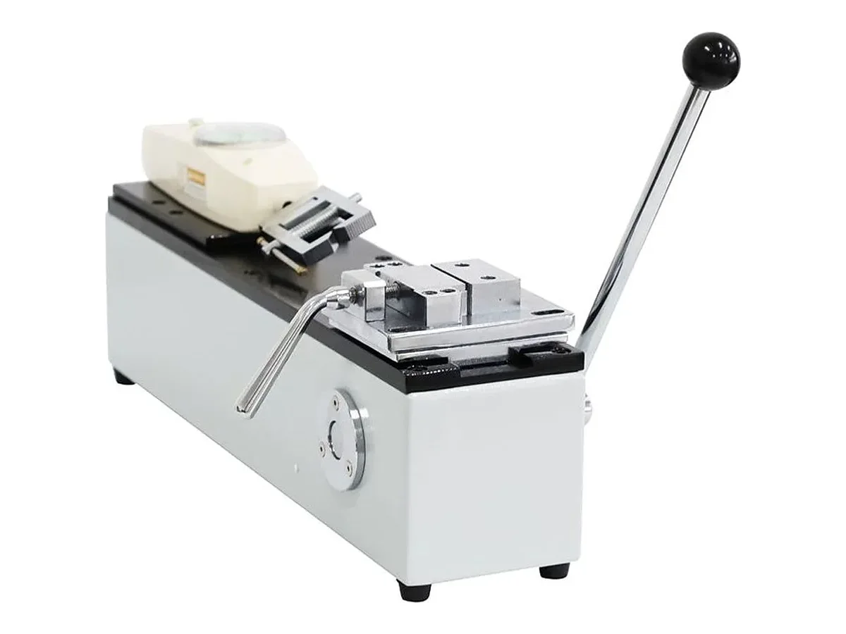
Ordinary crimped terminals fail far below 500 N, so a 500 N-class instrument reads them in the healthy middle of its scale — that is where accuracy lives. Put the same crimp on a 5,000 N frame and the reading sits in the bottom few percent of range, where every class-of-accuracy figure is at its worst. So: routine crimp verification belongs on the WM-817 (manual) or the WM-820 (automatic, records UL values); heavy lugs and thick-wire crimps go to the WM-811 with its 10–10,000 N range and motorized 10–600 mm/min pull; and the WM-812 is a 5,000 N dual-column universal frame for tension, compression, flexure, shear and peel — a materials-lab instrument, not a crimp spot-checker. For connectors, the WM-830 measures push-pull load, insertion force and pull-off vertically.
| Machine | What it tests | Range / resolution | Speed | Pick it for |
|---|---|---|---|---|
| WM-817 | Terminal pull-off, manual | 500 N, dial gauge | Manual | Spot checks beside the press |
| WM-820 | Terminal pull-off, automatic | 0–500 N (1,000 N custom), ±0.04 N | 10–800 mm/min | UL values and non-destructive mode on a touchscreen |
| WM-811 | Wire & lug tensile, auto clamping | 10–10,000 N, 70 mm stroke | 10–600 mm/min | Heavy lugs and thick-wire crimps |
| WM-812 | Universal tension/compression/flexure/shear/peel | 5,000 N, class 0.5, 1/100,000 resolution | — | Materials-lab work on a dual-column frame |
| WM-830 | Push-pull load, insertion & pull-off | — | — | Connector mating forces, vertical layout |
| WM-813 | Crimp cross-section analysis | 30–312X; 0.01–30 mm² (150 mm² option) | — | Metallurgical evidence: compression, voids, burrs |
| WM-818 | Cross-section, integrated cut & grind | 30–312X; 0.01–33 mm² (max 120 mm²) | — | One benchtop unit from cut to measurement |
| WM-814 | Harness conduction & insulation | 128 points; 0.1–50 Ω; 1 MΩ–1 GΩ; DC 200–700 V | — | Full-harness electrical sign-off |
| WM-823 | Power cord plug testing | DC 500 V insulation; 2–200 MΩ, six levels | Times freely set | Polarity, insulation and hi-pot on two heads |
| WM-815 | Vision: color, sequence, insertion | Connector ≤50 mm wide | < 0.2 s per piece | Catch wrong-cavity wires without touching them |
| WM-816 | Vision: two-row connectors | — | 0.25 s | Color-order verification on double rows |
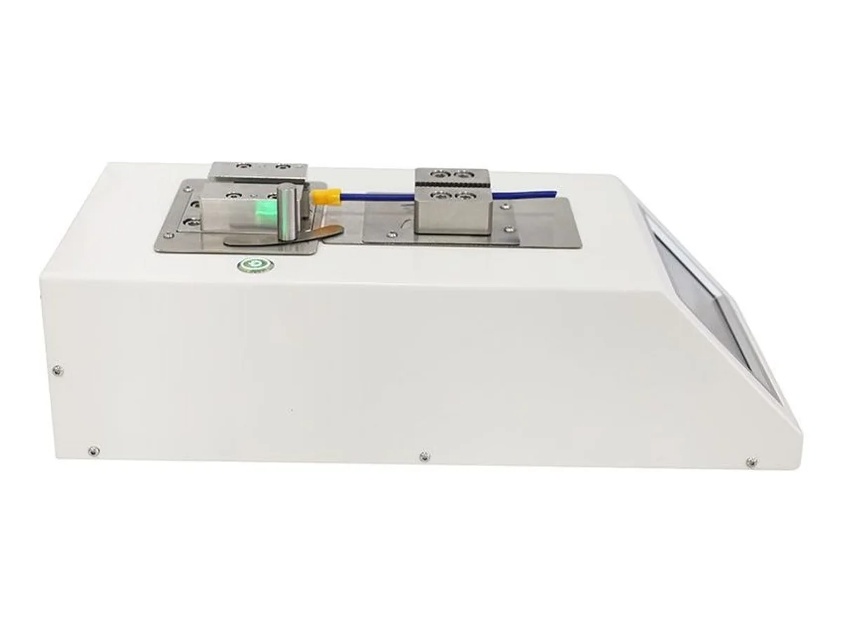
The 500 N class. Ordinary crimps break far below 500 N, so that scale reads them mid-range where accuracy is best — the WM-817 for manual spot checks, the WM-820 for automatic testing with ±0.04 N accuracy, UL test values and a non-destructive mode. Reserve the 10,000 N WM-811 for heavy lugs, and the 5,000 N WM-812 universal frame for materials work — putting a small crimp on a big frame parks the reading in the worst few percent of its range.
Why a crimp is good or bad, not just whether it held. The analyzer cuts through the joint, grinds and etches the face, and measures it at 30–312X: compression ratio, voids between strands, burr height, wing symmetry. A crimp can pass a pull test today and still show the voids that will fail it after vibration — that evidence only appears in the section.
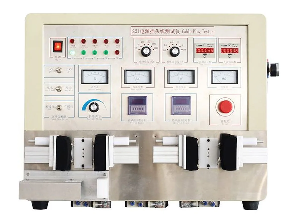
The WM-814 tests up to 128 points in one hookup: conduction from 0.1 to 50 Ω, insulation from 1 MΩ to 1 GΩ, and high voltage at DC 200–700 V / AC 100–500 V, with component testing in the same pass. For finished power cords with molded plugs, the WM-823 adds polarity and hi-pot testing on two heads.
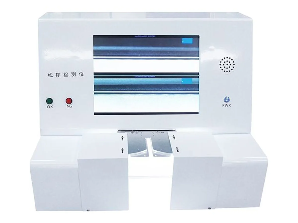
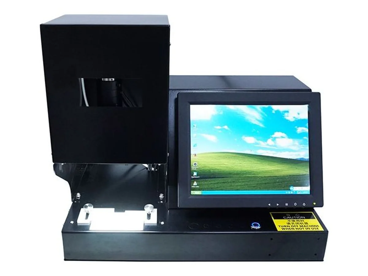
Wrong color order, wrong cavity, missing or half-inserted wires — verified optically in under 0.2 s (WM-815) or 0.25 s for two-row connectors (WM-816), with the part placed freely in the frame. They inspect; they do not touch or stress the harness.
For pull testers and cross-section analyzers: your terminal and wire samples, crimped. For continuity testers: the connector pin map and point count. For vision systems: the connector and its color scheme. State target throughput, then courier the samples — we run your parts on the actual machine, on camera, before you order.
Engineering guidance for choosing this process and correcting the defects that affect finished-wire quality.
Selection guide
Plan wire harness production from the drawing: cutting, stripping, seals, crimping, housing insertion, taping and final electrical checks.
Read engineering guide →Troubleshooting guide
Find why a crimped terminal backs out of its connector housing. Check part matching, orientation, crimp shape, primary retention and secondary locks.
Read engineering guide →Selection guide
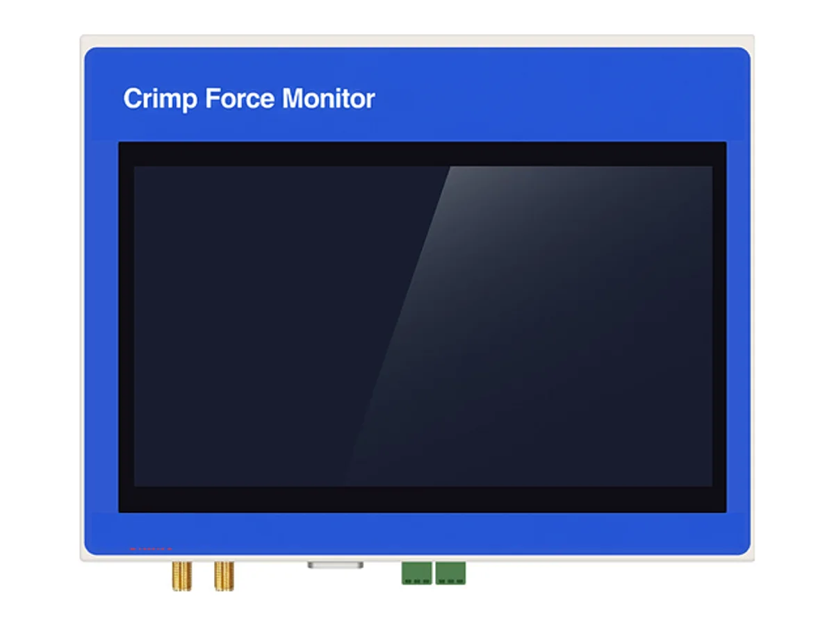
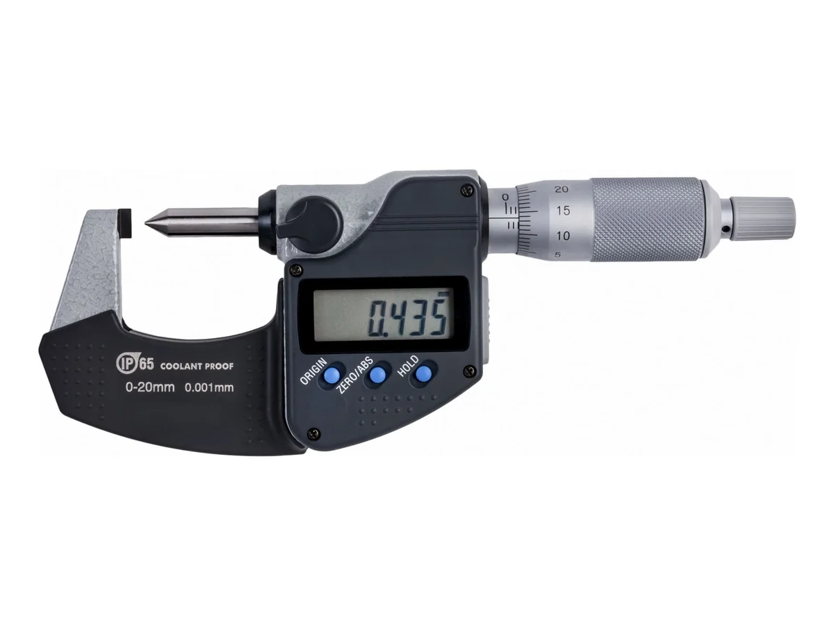
Build a crimp quality plan that combines force monitoring, pull testing, crimp-height measurement and cross-section analysis without confusing their limits.
Read engineering guide →Selection guide
Prepare wire samples, drawings and acceptance criteria for a useful machine trial. Record quality, accepted output and changeover without relying on a demo clip.
Read engineering guide →Selection guide
Choose a terminal crimping machine by terminal presentation, wire range, applicator standard, required process steps, inspection method and production mix.
Read engineering guide →Troubleshooting guide
Diagnose conductor nicks, incomplete strips, pulled strands, insulation stretch, length variation and feed marks in wire stripping operations.
Read engineering guide →Troubleshooting guide
Troubleshoot low pull force, incorrect crimp height, strand loss, bellmouth defects, insulation support problems and inconsistent terminal feeding.
Read engineering guide →Selection guide
Choose a coaxial cable stripping machine by layer construction, cable diameter, strip sequence, cut-depth control, end geometry and production architecture.
Read engineering guide →Troubleshooting guide
Troubleshoot cut braid strands, torn foil, marked dielectric, nicked centre conductors, incomplete pull-off and inconsistent strip length.
Read engineering guide →Selection guide
Select harness testing equipment by test points, two-wire or four-wire resistance measurement, insulation and withstand limits, fixtures and inspection scope.
Read engineering guide →Troubleshooting guide
Diagnose open circuits, shorts, high resistance, insulation failures, intermittent contacts, wrong cavity insertion and unstable harness test fixtures.
Read engineering guide →Troubleshooting guide
Troubleshoot weak wire splices, cut strands, excessive flash, incomplete bonding, unstable weld energy, tool marking and conductor contamination.
Read engineering guide →Selection guide
Choose ultrasonic wire welding equipment by conductor material, gathered cross-section, splice geometry, weld power, tooling, recipe control and acceptance testing.
Read engineering guide →Troubleshooting guide
Two bags of terminals marked 22 AWG can need different dies. What decides the match — barrel shape, insulation crimp, tab geometry — how to send terminals for a die fit, and how many crimps a year justify a press instead of a hand tool.
Read engineering guide →